2018-2019
Gearbox Internals
Cornell Baja
Scroll ↓
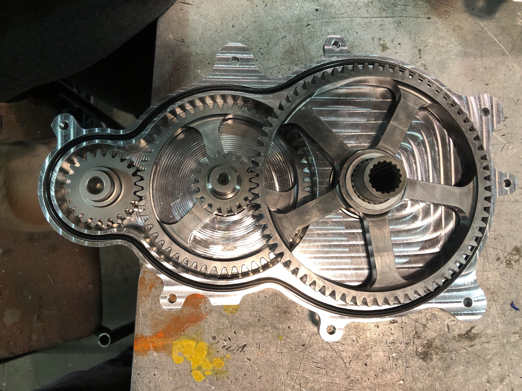
During the 2018-2019 season I designed the gearbox for our competition vehicle. As one would expect, the purpose of the gearbox is to transfer engine power from the CVT to the vehicle’s half-shafts while scaling torque and speed.
When designing the assembly, I took a blank slate approach rather than leaning too heavily on pre-existing work. Thus, I outlined the following objectives and constraints:
Constraints:
Package within rear frame
Weather and oil sealed
Must withstand shock and cyclic operational loads
Use readily available materials
Utilize standard pressure angles and pitches
Objectives:
Minimize mass, inertia, and envelope
Streamline gear selection process
Maintain comparable cost as previous years
Spur gears were chosen since they are more efficient and simple compared to other options like chain drive or helical gears. Those options increase complexity and mass with thrust bearings and chain tensioners. A two-stage reduction was also chosen since a single stage could not be practically packaged in the rear frame, and the packaging or high mechanical advantages of a planetary system were unnecessary.
After the type of reduction was selected, I was able to innovate on several key areas of the design. The most major are outlined below:
Gear Selection:
The first innovation was streamlining the gear selection process. I wrote MATLAB code to generate potential gear sets, determine the necessary face width of the gear, and sort based on total rotational and linear kinetic energy.
The face width of the gears were determined using AGMA strength equations for both tooth bending and pitting. The code also featured a number of built-in constraints, such as only using standard pressure angles and diametral pitch.
Material Selection and Heat Treatment:
During the previous competition season, the gears experienced a brittle fracture failure. Root cause analysis indicated that this was primarily due to the material and heat treatment. Generally, steel in gearing applications should not exceed a 0.5% carbon content. The previous gearset carburized 1045 carbon steel (0.45%), which significantly compromised the material’s toughness. I then identified three possible paths:
Carburizing low alloy steels was chosen as it would result in the lightest gears. From here, an investigation of viable materials was conducted. 8620 and 9310 were identified as the most promising. 9310 had a higher hardenability but was less available and more costly. Thus, 8620 was used for the gears and 9310 was used for only the pinions that are smaller and see a higher number of cycles. The cost increase from the previous year was minimal with this approach.
Finite Element Analysis:
There were a number of improvements made to the analysis setup to properly represent the interface and further reduce the mass.
The most major improvement to the analysis was representing a shaft rather than fixing the interface in ANSYS. Two examples of gears from the previous season are shown below. On the left, the interface is fixed with no shaft. It appears as if there is zero stress with this boundary condition. However, on the right a shaft is modelled and displays a significant amount of stress. This change was reflected in the analysis for my gearbox design, and I modelled the shafts at the least material condition to further amplify the stress.
Previous gearbox with fixed constraint at shaft
Previous gearbox with shaft modelled
The other major change was using a parameter study in ANSYS to iterate between multiple spoke thicknesses and geometries. The chart shown outputs the max stress and mass of the gears in order to display the optimal combination.
Other Design Improvements:
A number of other improvements were made to the design. First, the torque transfer interfaces were changed. I chose to either cut gear teeth directly onto the shafts or use involute splines. Both of these minimize the form factor of the gears since a large interface like a keyway or the previously used “trilobes” would not be required.
Also, asymmetric bearings were used based on the differences in reaction loads on each side of the shaft. This reduced the weight by an additional 0.26 lb.
Manufacturing Process:
Lastly, many of the manufacturing processes needed to be changed based on the new design. First, in previous years we designed the gear set to use off-the-shelf options. However, these were mainly available in medium carbon steels and not low alloy steels like mentioned before. So, I pursued a sponsor in Gleason to cut the teeth and heat treat the gear blanks that we created. They used a hobbing process, as shown in the video.
Additionally, since the torque transfer interfaces were changed to involute splines, a new method needed to be chosen to make the interface. We already had experience making the male spline on a rotary unit, but the female spline was uncharted territory. We considered broaching and wire EDM, but ultimately chose plunge EDM as it was available on campus. This was also reflected in machining fixtures, which located off the center bore.
Lastly, the materials were normalized before machining. This was to reduce residual stress on the part in case this contributed to the previous brittle fracture failures.
Overall, these design changes resulted in a 30% reduction in mass while also increasing the amount of mechanical advantage at the final drive. It was successful in competition and greatly improved the team’s process.


